CF can directly press the host self-decoding extension wiring instructions
1. Instructions for system use
Suitable for a variety of wiring situations.
The system supports a maximum of 32 households with eight floors and four households
The voice is clear and the fidelity is high
15 kinds of six chord ringtones are optional, and each household can choose freely
Support multi-household monitoring; Supports visual and non-visual mixing
The most power-saving product on the market, advanced green energy-saving design power consumption: backup battery power supply for voice system in case of power failure.
Standby 0.25W, ringing 1W, talk 0.35W, greatly extending the battery working time.
2. Wiring instructions
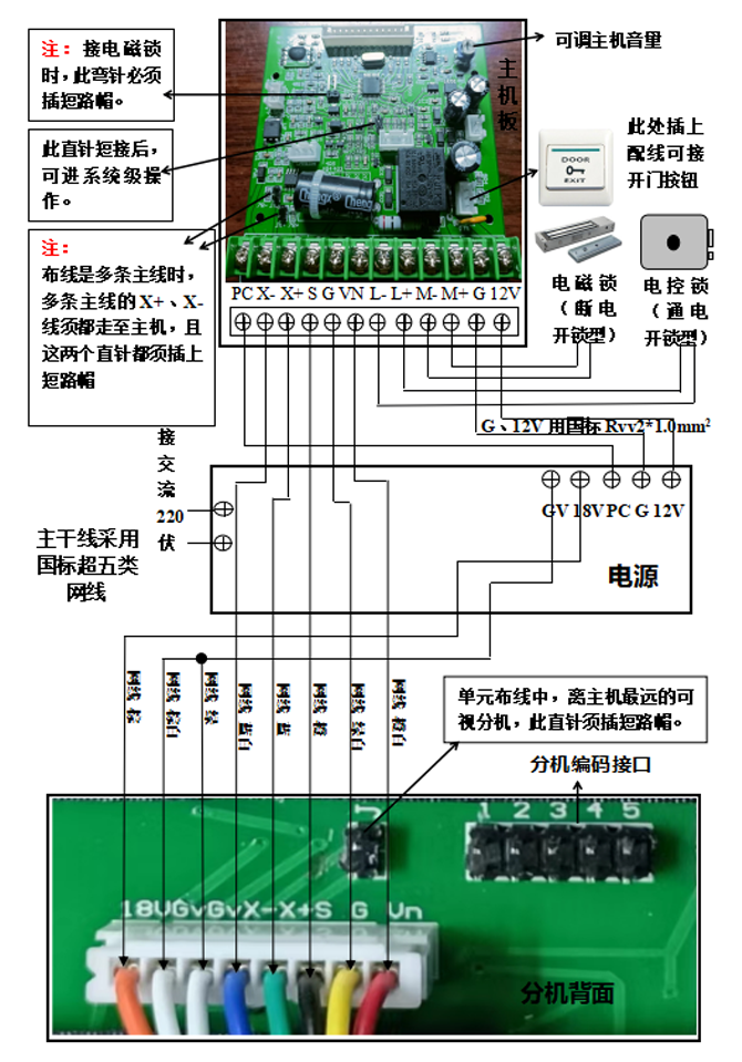
Description of the general wiring frame: the unit main line and the entry line are using the national standard super five network cables, five network cables used in the main line are connected to the host, and three are connected to the power supply.

(1) Installation and wiring methods of the host
- Take out the bottom shell of the main engine, fix the bottom shell on the position installed on the wall (it is recommended that the lower edge of the main engine is 1.5m from the ground), and draw the position of the four screw holes of the bottom shell with a pencil. Then use an electric drill to drill all the mounting holes to size.

2. Fix the bottom shell on the wall with the expansion tube and screws.
3, the bottom shell of the host is pasted with the wiring of the door opening button.
4, the host terminal X-connection network cable (main line) blue and white line;
Host terminal X+ Network cable (trunk line) Blue line;
Host terminal S Network cable (trunk line) Orange cable;
Host terminal G Network cable (main trunk) Green and white cable;
Host terminal Vn Network cable (trunk line) Orange and white cable;
Connect the host terminal PC to the power supply PC;
Host terminal G is connected to power supply G;
The host wiring terminal connects 12V to the power supply.
5. the host terminal L-, L+ control electric control lock (power unlock type); The host terminal M-, M+ control the electromagnetic lock (power off unlock type) (When connecting the electromagnetic lock, the bending pin of the host board must be inserted into the short-circuit cap). The locking cable adopts the national standard Rvv2*1.0mm2.
6. Install the host face cover on the bottom shell of the host and lock it with screws.
(2) Installation and wiring method of visual power supply
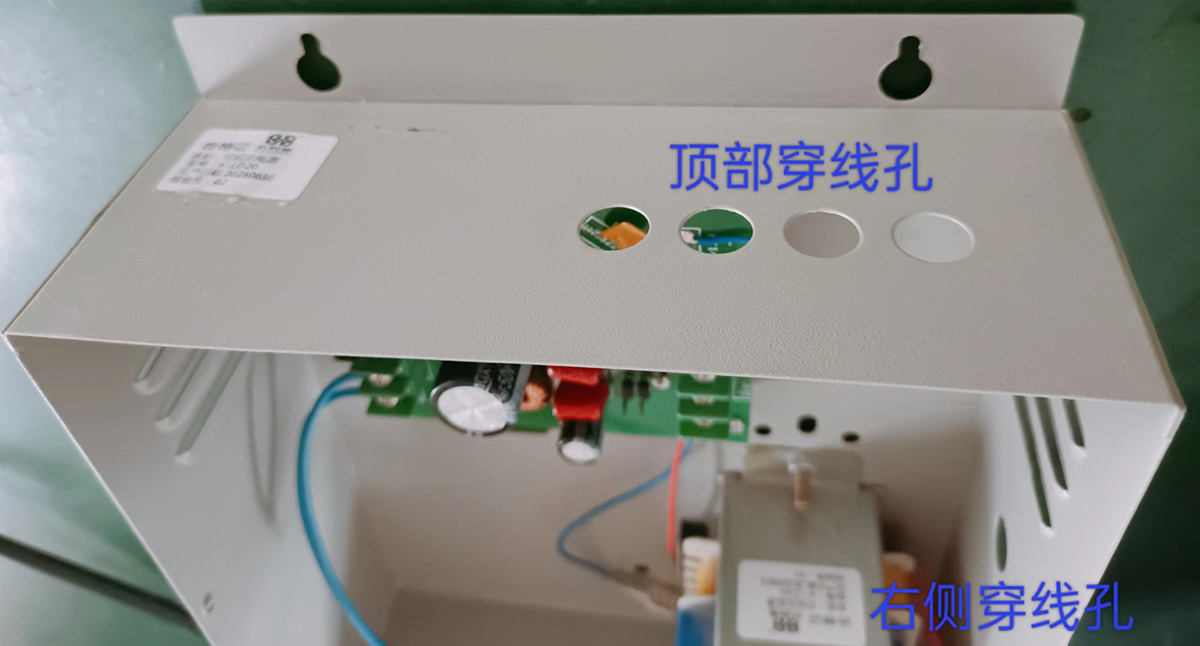
1. The bottom edge of the power box is 2.5m away from the ground according to the installation holes shown in the following figure. If it is in a weak electric well, the lower edge is 1m from the ground. Use an electric drill to drill mounting holes in the wall to size. Then use the expansion tube and screws to fix the power supply housing.
2. Open the front cover of the power supply housing, and the red wire of the transformer is connected to the 220V power cable.
3. Connect the PC, 12V, and G cables of the power supply to the PC, 12V, and G cables of the host. The cable diameter must be 1.0mm2.
4. The main trunk is routed through the power cable hole. The brown cable of the main trunk connects to the power wiring terminal 18V, and the brown, white and green cable connects to the power wiring terminal Gv. The main trunk routes out of the power cable hole to the host, and connects the other five core cables to the corresponding wiring terminals of the host.
(3) Installation and wiring methods of the video extension
The extension is equipped with hanging plates. Use a pencil to draw the two screw holes (four mounting holes, up and down or left and right holes) of the hanging plates on the wall (it is recommended that the lower part of the extension be 5m from the ground). Then use the electric drill to make the installation hole according to the size, make the screw, and hang the bottom shell of the extension on the hanging plate.
The extension is connected to the main line.
The wiring method of the extension cable and the entry cable is shown in the following table:
The method of connecting network cables to video extension cables
|
Network cable color |
Orange white |
Greenish white |
orange |
blue |
Blue and white |
Brown, white and green |
brown |
|
Line symbol |
VN |
G |
S |
V+ |
V— |
GV |
18V |
|
Line color |
red |
yellow |
black |
green |
blue |
white |
orange |
The coding table of the extension coding interface is as follows:
"◆" indicates that the short circuit cap is inserted, and a space indicates that the short circuit cap is removed.
|
Bouncing pin |
1 |
2 |
3 |
4 |
5 |
Bouncing pin |
1 |
2 |
3 |
4 |
5 |
Bouncing pin |
1 |
2 |
3 |
4 |
5 |
Bouncing pin |
1 |
2 |
3 |
4 |
5 |
|
101 |
|
|
|
|
|
102 |
◆ |
|
|
|
|
103 |
|
◆ |
|
|
|
104 |
◆ |
◆ |
|
|
|
|
201 |
|
|
◆ |
|
|
202 |
◆ |
|
◆ |
|
|
203 |
|
◆ |
◆ |
|
|
204 |
◆ |
◆ |
◆ |
|
|
|
301 |
|
|
|
◆ |
|
302 |
◆ |
|
|
◆ |
|
303 |
|
◆ |
|
◆ |
|
304 |
◆ |
◆ |
|
◆ |
|
|
401 |
|
|
◆ |
◆ |
|
402 |
◆ |
|
◆ |
◆ |
|
403 |
|
◆ |
◆ |
◆ |
|
404 |
◆ |
◆ |
◆ |
◆ |
|
|
501 |
|
|
|
|
◆ |
502 |
◆ |
|
|
|
◆ |
503 |
|
◆ |
|
|
◆ |
504 |
◆ |
◆ |
|
|
◆ |
|
601 |
|
|
◆ |
|
◆ |
602 |
◆ |
|
◆ |
|
◆ |
603 |
|
◆ |
◆ |
|
◆ |
604 |
◆ |
◆ |
◆ |
|
◆ |
|
701 |
|
|
|
◆ |
◆ |
702 |
◆ |
|
|
◆ |
◆ |
703 |
|
◆ |
|
◆ |
◆ |
704 |
◆ |
◆ |
|
◆ |
◆ |
|
801 |
|
|
◆ |
◆ |
◆ |
802 |
◆ |
|
◆ |
◆ |
◆ |
803 |
|
◆ |
◆ |
◆ |
◆ |
804 |
◆ |
◆ |
◆ |
◆ |
◆ |


